Hardware 1
This guide will assist you through the design of the electrical circuitry required to regulate power within your physical robotic system. We will explore the theory pertaining to the selection of appropriate electrical components, particularly integrated circuits (ICs), inductors and capacitors. We will also demonstrate the processes you should be following to select correct electrical components in the context of a switching regulator for stepping-down voltages (i.e. a buck converter). This will be particularly useful for powering components which require less than the 7.4V nominal voltage supplied by your batteries.
The process we will employ is largely transferable to the design of a circuit to step-up voltages (i.e. a boost converter). However, if your group decides to use a boost converter for any purpose within the project, you will need to establish your own design parameters. Keep in mind that you should design for a safe maximum of around 50V, since we cannot test any circuits which may exceed 60V. More information regarding boost circuit design can be found here and here.
Voltage Regulation Basics
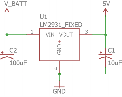
Voltage regulators are a critical part of any electrical circuit, and are used to convert an input voltage into a desired output voltage. There are various types of voltage regulators. You have probably used a linear voltage regulator, like the LM7805, to regulate an input voltage to 5 volts. However, linear regulators have two disadvantages. Firstly, they can only step-down voltages, and secondly, they can be very inefficient (depending on the input and output voltages). Switching regulators are far more useful in comparison to linear regulators. Switching regulators can reach efficiencies of up to 90%, and have the ability to either step-down or step-up voltages. Unfortunately, switching regulators require a few extra components, and are slightly more complex, as shown through the schematics below.
There are several types of switching regulators that allow you to perform various voltage conversions. These different types are known as topologies. The topologies of a switching regulator include:
- Buck Converters - used to step-down to a fixed voltage.
- Boost Converters - used to step-up to a fixed voltage.
- Buck-Boost Converters - used to either step-up or step-down a voltage to a fixed voltage.
Inductor Basics
The inductor is the critical component that underpins switching regulators. When a voltage is applied across an inductor, the current through the inductor behaves based on the equation:
V ⁄ L = di ⁄ dt

# Where
V = the voltage across the inductor
L = the inductor value in Henries
di = the change in current in Amps
dt = the change in time in seconds
Put simply, if a fixed voltage is applied to a fixed value inductor, then the current through the inductor will ramp up linearly with time. However, one of the most important aspects of the inductor is its behaviour when the voltage is removed. When a voltage across an inductor is removed, the inductor tries to keep the current flow constant. This means that the inductor will "generate" its own voltage to keep the same current flow. This phenomonem is what powers switch converters (pun intended).
Designing a Switching Regulator
Now, you do not need to design a switching regulator completely from scratch. Like a linear regulator, you will choose an IC that applies to your application and then add in surrounding components to suit. However, there is a bit more work involved in selecting the surrounding components within a switching regulator. The main component we need to select is the inductor.
For this example we are going to design a buck (step-down) converter that regulates a 2 cell LiPo battery (6.4-8.4 volts) down to 5 volts with a 2.5 Amp maximum output. The first thing we need to check is that the required duty cycle for our application is indeed possible (i.e. between 0 and 100%, or as stated in the regulator's datasheet). The equation to calculate the duty cycle can vary based on the topology you choose, but it only depends on the input and output voltages. The formulas to determine the duty cycle for a boost or buck converter are below. It should also be noted that with most switching regulators we cannot have duty cycles below or above a given threshold. This threshold is typically outlined in the switching regulator's datasheet, but typically if your required duty cycle is anywhere between 10-90% it should be fine.
Dbuck = Vout ⁄ Vinput
Dboost = (Vout - Vinput) ⁄ Vout
Choosing a Switching IC
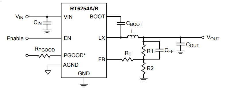
The first step to designing our buck converter is choosing an IC to use. There are many manufacturers and they all have different properties. You will need to ensure that the input voltage, output voltage, and the maximum current are all suitable for your application. Additionally, we recommend you find one with voltage, thermal and short-circuit protection circuitry. Furthermore, ensure that the IC package is something that you will be able to solder. For this guide we have selected the RichTek RT6254B buck converter, for which the datasheet can be found here.
Make sure when you are selecting your IC, you read through the datasheet before committing to one. Why? Well it is critical you understand the datasheet, and if you do not, it will make it extremely difficult to design your switching regulator. The main thing to understand is the section about component selection. If you find this section to hard to follow, do not select that particular IC. Another good thing to look out for is if the datasheet already includes some suggested component values for different situations. For example, take a look at page 7 on the RichTek datasheet, where you should see a table of suggested inductor/capacitor/resistor values. You should not necessarily use these values, rather you should calculate your own, but they provide a good ball park estimate to validate your calculations.
We are now going to go through and select the required components for the RichTek regulator, with the aim of stepping down our 2 cell 7.4V LiPo to 5V at 2.5A. If you scroll down to page 11 of the datasheet, you will get to the section titled 'Application Information' which details how we go about selecting our components. Check out the typical application circuit diagram, shown below, to see the circuit we will be designing and some of the components we need to choose.
Important: When selecting components, ensure they are in stock, and that you will be able to solder them by hand. Also remember the components you select will depend on your chosen regulator, so you will need to read through the datasheet notes to aid your selection process.
Inductor Selection
The first thing the datasheet discusses, in regards to components, is how to select a suitable inductor. To determine the value of the inductor, the datasheet provides the following formula.
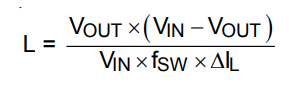
For our scenario, we have Vout equal to 5V, Vin can be anywhere between 6.4 to 8.4V (we will use the nominal battery voltage of 7.4V though), a switching frequency (fsw) of 500kHz and a ripple current (ΔI) of 1.2A. Based on these values, using the equation above, we can calculate the inductor value to be 2.7uH.
Now we can determine the peak inductor current. This is important to know as we need to select an inductor with a saturation current above this value, and we must ensure the IC can handle this peak current too (the table on page 6 shows the current limit for this particular IC). To calculate the inductor peak current, the datasheet provides us with the following formula.
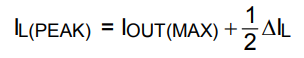
Using this formula, we can determine the peak current for our example circuit to be 4.6 Amps (Iout max was set to 4 Amps as per page 1 of the datasheet). We need to double check that this value is less than the IC current limit, which it is, so we can continue on with our design.
We will now choose an inductor with a value of approximately 2.7uH, and ensure that its saturation current is greater than 4.6 Amps. For the purposes of this example, we went and found the following inductor. This is a 2.7uH inductor with a current rating of 6.6A and a saturation current of 9.6A, which should be fine for our application.
Important: If you select an inductor with a value that is not exactly what you calculated, you will need to go back and recalculate the inductor ripple and peak current to ensure these values are within the limits.
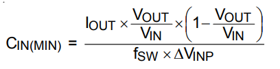
Input Capacitor Selection
The next step is to determine the value of the input capacitor. This value can be calculated using the following formula. Using an Iout value of 3A and an input voltage ripple of 200mV, we determine the minimum capacitor value to be 6.6uF.
Since our minimum capacitor value is less then 10uF we are going to follow the datasheet's recommendation which states "... the typical operating circuit used two 10uF low ESR ceramic capacitors on the VIN pin [in parallel] and an additional 0.1uF capacitor is recommend to be placed as close as possible to the IC input side for high frequency filtering." ESR stands for equivalent series resistance. The ESR for a ceramic capacitor is anywhere between 5 and 100mOhms, but can typically be found in a graph within the characteristics sheet for the capacitor. The ESR is dependent on the operating frequency. A low ESR is typically less than 10mOhms. For this design we will use two of these 10uF capacitors which have an approximate ESR of 5mOhms at 500kHz. The ESR was approximated from the characteristic sheet.
Important: Ensure that the capacitor you select is rated for at least double the voltage that will be across it. In this example the maximum input voltage is ~8V and so we have ensured that the capacitor voltage rating is equal to or greater than 16V (including a two-fold safety factor).
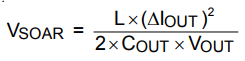
Output Capacitor Selection
The value of the output capacitor is dependent on the desired output ripple voltage and the transient of the output when the the load changes. The output ripple voltage is how much "noise" you are willing to have on the output side. The transient is how quickly you want the converter to react to changes in the load. Changes in the load are when the current draw of the output side changes. This is only a problem if the load current draw changes abruptly.
For this example, will use the recommend capacitor values from the table on page 7, and will check the corresponding ripple voltage and transient voltages are appropriate for our application. The datasheet says in a typical application to use two low ESR 22uF capacitors in parallel. So we will use two of these 22uF capacitors which have an ESR of approximately 6mOhms. The ESR was approximated from the ESR Graph within the capacitor's characteristic sheet, using a frequency of 500kHz.
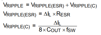
We now need to calculate the output ripple voltage, which can be found using the formulas from the datasheet, as presented below.
Feed Forward Capacitor
The feed forward capacitor can help in high voltage applications by speeding up the transient response without affecting the circuit's stability. We probably do not need this for our application, and as stated by the datasheet we will simply use a capacitor with a value between 47-82pF. Not all switching regulators will have this component.
The Enable and Power Good Pin
Most switching regulators have an enable pin. The enable pin typically needs to be pulled high to allow the regulator to actually turn-on and regulate the voltage. In this application we simply want the regulator to start regulating as soon as the power is turned on. For automatic start-up we simply tie the enable (EN) pin to the VIN pin via a 100kOhm resistor, as suggested in the datasheet.
Many switching regulators also have a power good pin. This power good pin goes high when the output voltage has settled. This can be useful for turning on electronics once the output voltage has stabilised. If you have read the datasheet correctly, you will have noticed one version of the switching regulator we have chosen does have a power good pin, while the other does not. For this example, we have chosen the one with the power good pin. Typically, you tie this power good pin to the enable pin of the IC you are regulating power for, or you tie it to a reset pin so the IC only "starts-up" after the voltage has settled. In our case the Raspberry Pi does not have any of these, so we are going to ignore it. However, one thing you could do is put a mosfet between the output side of the switching regulator and the Raspberry Pi, and use the power good pin to switch the mosfet on/off.
Setting the Output Voltage
If you have chosen a switching regulator IC that has an adjustable output voltage like we have, you will need to "tell" the regulator what voltage it needs to output. To "tell" a switching regulator IC what output voltage to try to generate, typically two resistors creating a voltage divider are used, with the voltage divider output being sent to a feedback (FB) pin. For the buck regulator previously selected, the datasheet provides us with the following formula.
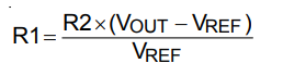
The datasheet states that we should use a 10k-100kOhm resistor for R2, and that Vref equals 0.6V. Therefore, for our application if we choose R2 to equal 100kOhm, then R1 would need to be 733kOhm. Additionally, the datasheet also states that we should ensure that the tolerance for R1 and R2 is 1% or better, and that they are no more than 5mm away from the feedback pin.
External Bootstrap Diode
We could also add in a diode between the BOOT and VIN pin. However, as stated by the datasheet this is only required when the input voltage is lower than 5.5V, which in our application it is not.
Final Notes
So we have now selected all the components that should allow the RichTek buck converter to generate a 5V output from our 2 cell LiPo with enough amperage to power the Raspberry Pi. However, there are some other components you may wish to include in the design. Such as a switch to turn on the system; you do not want to have to keep plugging/unplugging the battery. You probably should also include a polarity protection diode after the switch to ensure if the battery, or another power supply, is plugged in incorrectly then you will not accidentally blow anything up. Remember that a diode has a forward voltage drop and so this will change the input voltage going into the IC, and will therefore change the values we have calculated here. You may wish to add LEDs on both the input and output side of the voltage regulator to indicate that the regulator is working correctly. Finally, you could use the fixed 5V output voltage from the buck converter in conjunction with a comparator circuit to turn on a LED if your battery is below a certain voltage.
The other thing that the teaching team would recommend is adding some standard pitch (0.1") 2 pin headers, with one pin connected to ground, and the other either connected to your 5V output voltage, or the 7.4V nominal input voltage. These should be connected after the switch and polarity protection diode for protection. Adding these headers will make it easier to power any other components that you decide to add on later. You may also wish to add a 3.3V regulator to your power board, and have a few 2 pin headers with 3.3V, remembering the Raspberry Pi GPIO pins operate at 3.3V.
Choosing Connectors and Wiring Boards
One of the critical aspects of any PCB is understanding how it will be used and how signals will be routed in and out of the board. Selecting suitable connectors and wiring your boards together properly can really make or break a project. By using the appropriate connectors and wiring scheme you can ensure that your robot is easy to assemble/disassemble, and can help mitigate errors. Additionally, if you choose the right connectors, you will minimize the potential for miscommunication regarding how the electrical systems are to be connected; the connectors/PCB can make it almost foolproof! As an example we will talk about the connectors and wiring we could use on a power board that utilise the RichTek buck converter.
Well first we need to connect our power supply to our board. However, before we go and select a connector we need to think about the types of power supplies that may be used. Well obviously we could use the supplied battery, but do we want to always use it? What about when you are simply doing some static testing (i.e. the robot is not moving around), do we want to be able to connect the board to a bench top power supply? The teaching team would personally answer yes to this question, so then the follow on question is how would a bench top power supply be connected to our power board? Well, the teaching team would construct or purchase a custom cable that plugs into the bench top power supply (i.e. uses 4mm banana plugs) and then uses the same connector as the battery (i.e. this one). Okay, so that is the input side to our power board, now what about the output side?
We now want to connect the 5V output voltage line of our power board to the micro USB power slot of the Raspberry Pi. The Pi side is obvious, we will use a hacked micro usb cable, however the power board side is up to you. We would highly recommend you use some form of polarised connector, and one that can handle at least 3A. The teaching team would personally use a Barrel Jack connector designed for a PCB such as this one.
The final thing to discuss is the switch. While yes you could have the switch soldered directly into the PCB this could make it extremely difficult to turn the robot on and off. Instead, you probably should have a 2 pin standard pitch (0.1") header on your board, and the reciprocal header soldered to wires connected to your switch. We would also recommend to have this colour coded, as in, if you use a blue header on your board, then use a blue connector wire to your switch. This will make it easier for you to communicate to another user how it all fits together, as well as for a user to intuitively understand how it connects together if you are not around.
By using the battery connector on the input side, the barrel jack on the other side with a custom barrel jack to micro USB cable, and a colour coded switch cable, we have created a wiring scheme that communicates its own purpose. This will mitigate avoidable mistakes, and ensure your team knows exactly how to use your system.
In EGB320 we often see teams having a large number of prototyping wires. However, having a large number of these can often lead to a wiring disaster. This also can make your own lives difficult. For example, it can make reassembly an absolute nightmare, and something you dread. It also makes it extremely hard to debug, because it will be difficult to tell if a single wire is slightly loose, or connected to the wrong pin. If you use a proper header (i.e. a 3 pin header for a 3 pin terminal), then you will get a more solid connection. If the wiring of your system is not intuitively able to be integrated with another system, you haven't demonstrated adequate engineering design. So ultimately you should be creating your own cables using the appropriate headers, and using ribbon cables when appropriate to keep all wires together, rather than simply using standard headers with a bunch of prototyping wires.
Manufacturing a PCB
PCB Design Software
Once you have a circuit you will need to create a schematic and then turn that schematic into a manufacturable PCB. In EGB320 you may use any PCB design software you like as long as it has the capabilities of producing Gerber files, however we will be supporting EagleCAD. The 3 standard PCB design software packages are:
- Eagle CAD - SparkFun has great tutorials on creating custom component footprints, drawing schematics, generating board layouts and advanced SMD PCB topics that we highly recommend you read through in detail. However, please use this job file when exporting your Gerber files.
- KiCAD - is a great piece of open source software.
- Altium - is the industry standard, but it is proprietry.